
After converting the room into a pinhole camera, students were given the task of designing a pinhole camera using a unique object, (i.e. something that is not a simple box). In order to do this our students had complete a number of tasks.
Students had to drill a pinhole ranging from 0.1 mm up to a maximum of 0.3 mm using a CNC router into a small sheet of copper metal. The router was used because the drill bits were extremely fine and fragile. Drilling by hand resulted in the breakage of a number of drill bits.
Next, the pinhole was scanned and the image was imported into Photoshop (images below).
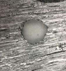
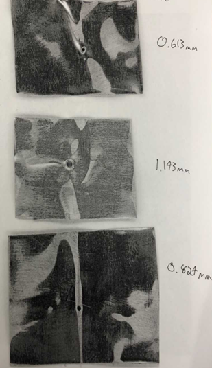
Using Photoshop, the students measured the diameter of the pinhole in pixels. Using the number of pixels per inch, students used dimensional analysis to convert the diameter into units of mm.
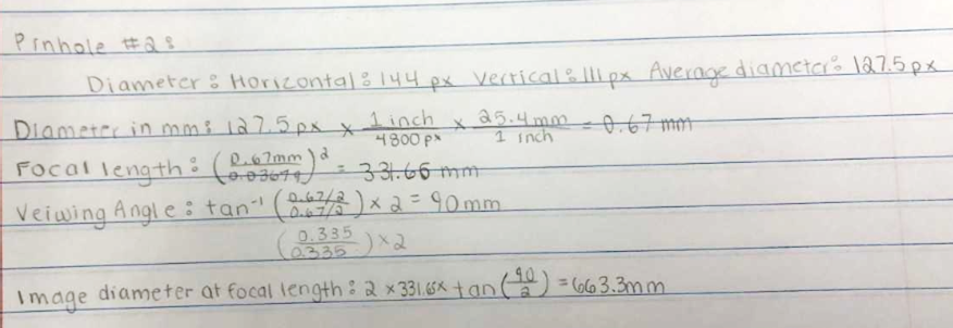
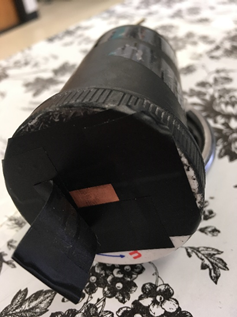
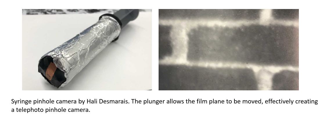
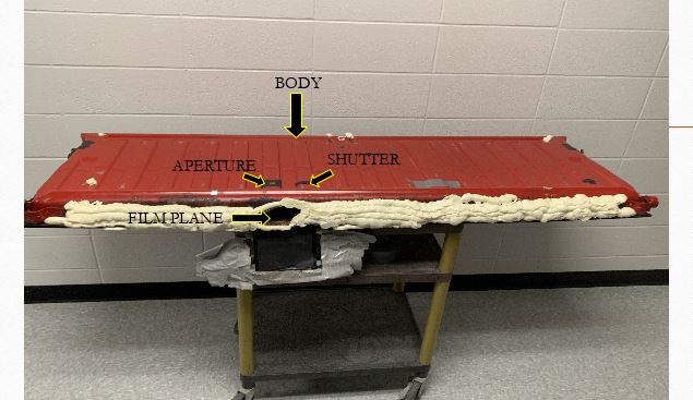
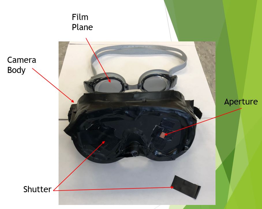
Once the pinhole diameter was known, students could calculate the focal length, the viewing angle, and the image diameter at the focal length for their pinhole. This helped them decide on an object that had a size large enough for the image they were trying to capture. They used this information to design their pinhole camera. An example of one of the student’s designs is shown below.

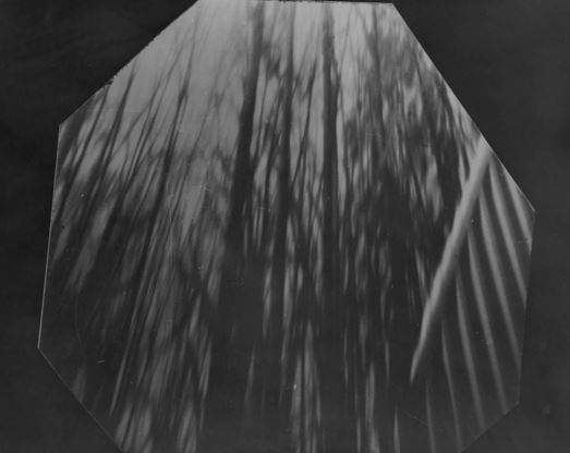
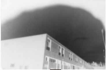
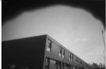
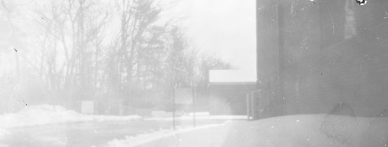
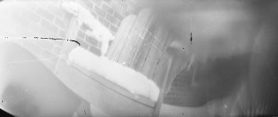
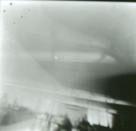
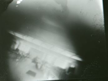
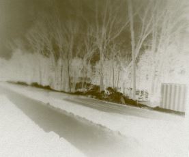
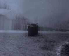
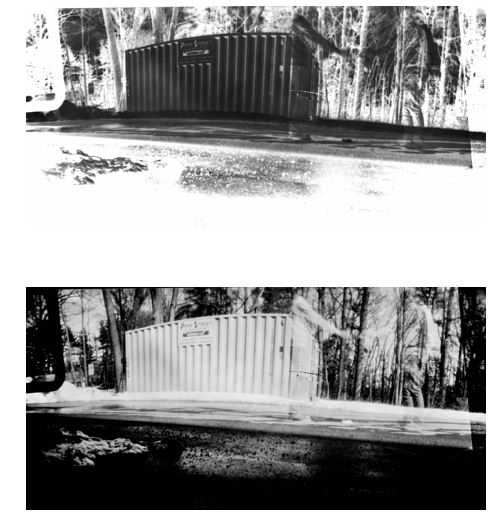
After they constructed their camera, they had to test it and modify it in order to get a negative that they could print in the dark room. In addition to making a physical print of the negative, they also created a digital print of the negative using Lightroom. The top image below is a camera made from an old medicine bottle. The second image is the negative made with the pinhole camera. And the bottom two images are the physical and digital prints of the image.
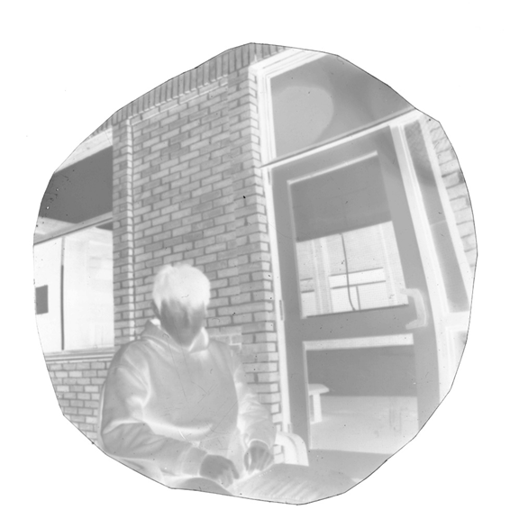

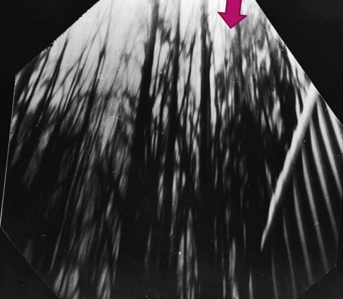
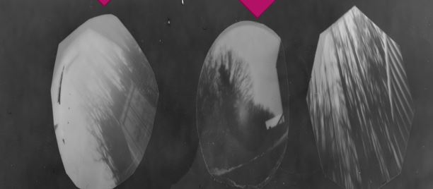
In the gallery below, we will be adding images of the students negatives and prints.

Leave a comment